Category: details

Hardware installation

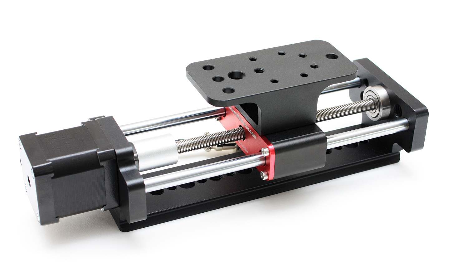
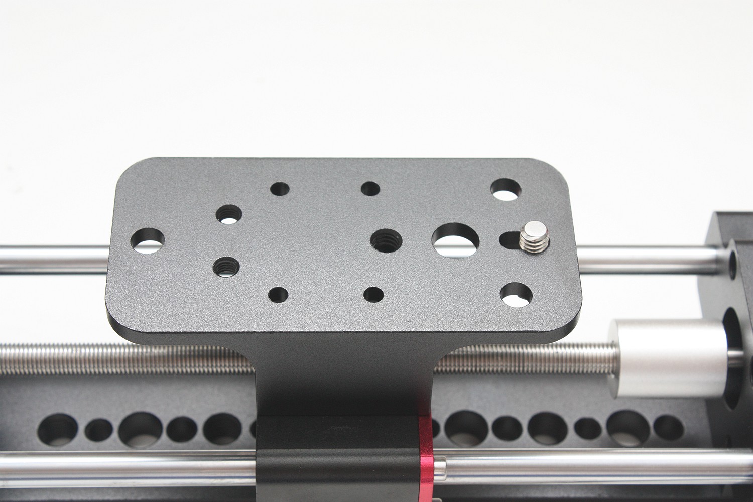
1,Install the camera on the rail by using 1/4 inch screw.

install1

install2

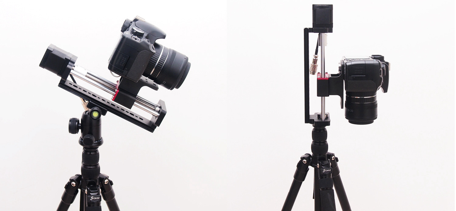
2,Install the rail on a tripod by using the screw hole in the rail bottom.There are 4 kinds of holes in bottom, 1/4 inch screw holes, 3/8 inch screw hole, 6.5 mm diameter and 10 mm diameter hole.Each kind of hole has four positions.

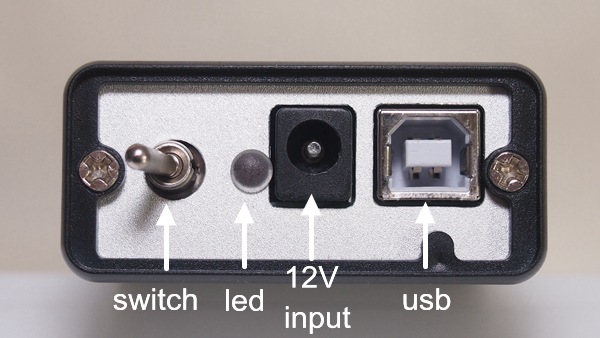
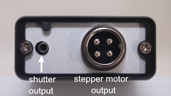
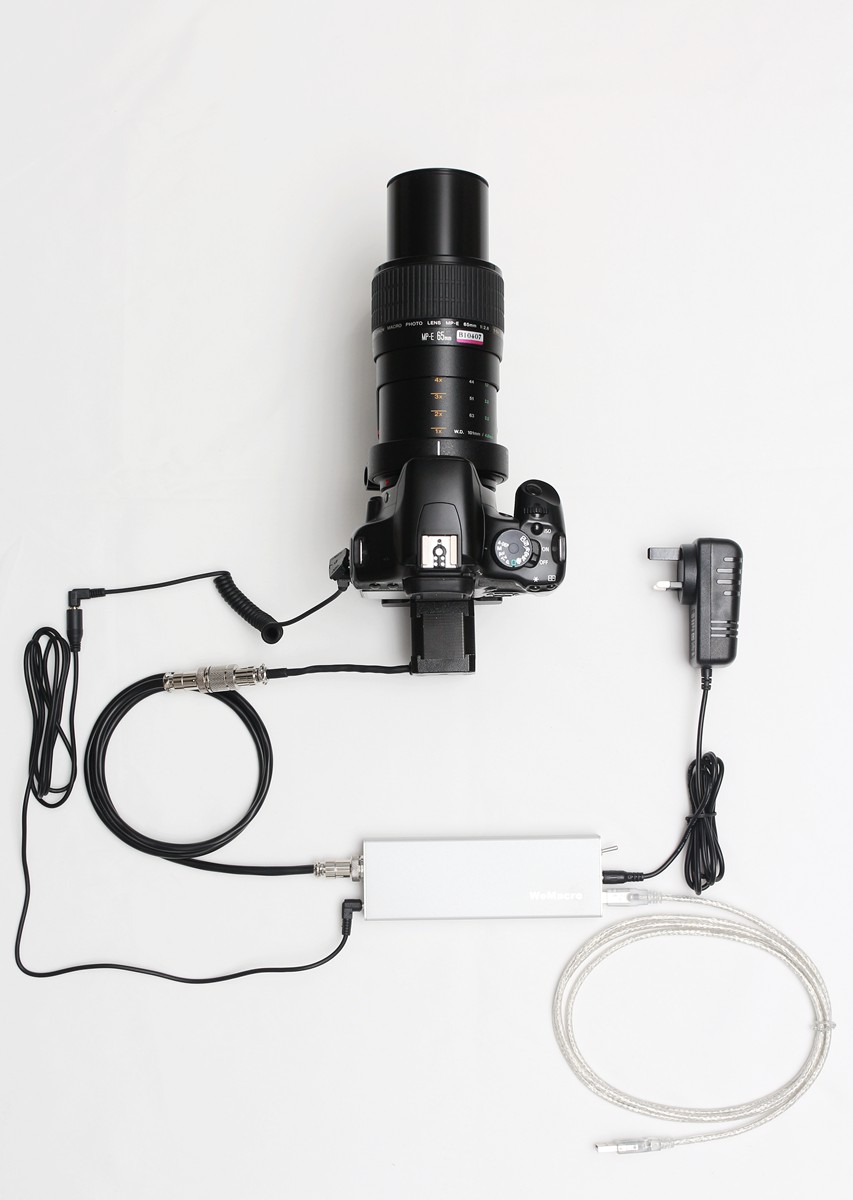
3,Connect the shutter extension cable to the control box,shutter cable connect to camera.Then connect these two cable
port1_e

port2_e

4,Connect the USB cable with computer and control box.Connect the stepper motor cable with control box and the rail.Be careful of the direction of the cable’s notch.
wire

The computer will notify that the system find a new hardware.Please install the driver.(microsoft Visual C runtime library support needed)

And we also provide holes at one side of rail to vertical install. 2 of 1/4 inches threaded holes and 3/8 inches threaded holes.If you want take photos on plants seeds or  sands,you can set it vertically.(Notice: The platform  wihich you put sand on it should not connect with the tripod,otherwise the shutter‘s vibration will make the sands moves in shooting. )

Notice:Please avoid running the platform to both rail’s edge . If it jams at the edge,turn off the power first,then rotate the  coupling by hand(counter-clockwise at motor side,clockwise at front side,look from motor side).

Diagram of cable connection (usb cable connect to PC if it‘s controlled by computer. )
install-demo


all install bs

brief_s

side


A little upgrade about how we install 1/4 inch bolt.Make it easier to install the camera since 2016 June.

IMG_0630

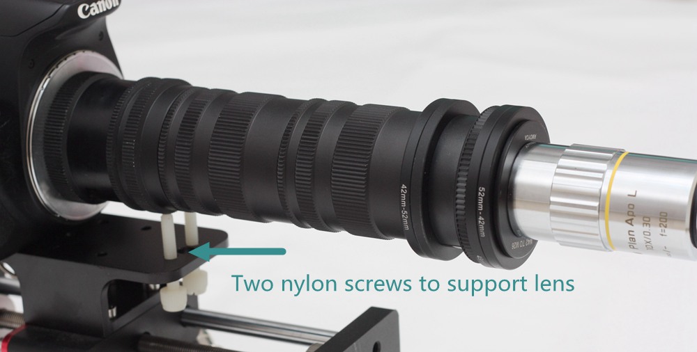
In front of the plate,there are two M5 thread hole,user can use 2 M5 nylon screws to support the lens.It will help to reduce the time of vibration which caused by mirror.The vibration will be obvious when the magnification is higher than 5X and the light is continuous light.
raynox-tube-lens-support

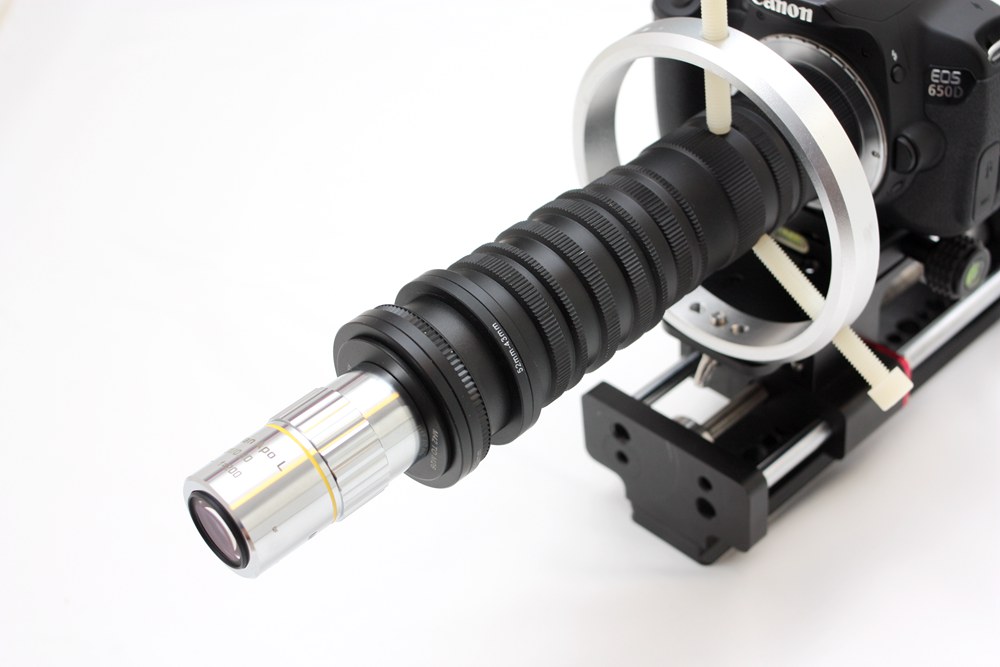
There is an optional parts, Ring support, which can reduce mirror’s vibration a lot.It will supply in the store.
ring


There are 4 types of holes in the rail bottom:1/4 inches threaded hole;3/8 inches threaded hole;10 mm diameter hole;6.5 mm diameter hole.Each of them have 4.
bottom


Software setting

The new PC software works in WinXP,Win7,Win8,Win10 system.

You can download the control software and driver at this page

Please turn on the control box first and connect it with usb cable.

Install driver first, ft232 driver or ch341ser.exe, then extract the whole wemacro folder to your computer. Double click wemacro.exe to run.

Press “F4” to switch language(chinese and english)

new soft

choose the relevant port in top left part,then click connect

port

You can find which port to choose in device manager page.

The port will show as below in device manager.

port2

The software now can provide 2 modes to work.The program is compatible with all version of control box.

1,Distance mode 

This means you only need to decide how long the total distance you want the rail move and how long the single step is.The program will calculate how many steps it will take.

new soft1

If you change” total distance”,the steps number will change accordingly.

If you change” step length”,the steps number will change accordingly also.Press “save” then you can adjust the lens position by pressing  forward or backward.When the camera reach the position,press “RUN” to start.It will show how long time it will take.The program also provide backlash compensation function.Tick “return” and press “Calibrate” after the rail return to the starting position.The rail will compensate the backlash by itself.

2,Start to End mode

Tick “Start to End”and “return”.Input single step length you want then press”Save”.Make sure there is “As start” button at right side.If it shows “As End” just press one time to switch it.

Then press forward or backward to adjust position.If you want to move fast,you can set 1mm as single step length.When the position is close to where you want to start,change back the step length and press forward(forward only) to reach the starting point.

Press “As start” to set as starting point.Then press forward and step forward to find ending point.(forward direction only).Press “As End” the rail will go back to starting point,then press “calibrate”to compensate. Now you can press “Run”to start.The program will do the rest. If you want to run one more time,please remember to press “Calibrate”after the rail go back to starting point.

NOTES

shutter waiting time“means the time between the rail travel and trigger the shutter in each step.Sometime it depends on the recharging time of flash light.

shutter per step“means how many times you want  in each step.It’s quite useful in HDR photography or Mirror lock-up.

Interval of shutters ”means if you set few times of shutter in each step.The gap between every shutter should longer than your exposure time..

“Backlash” Please set it to 220 micron.

Also you can save the setting or load the setting which you used before.

Notice:The shutter signal may be affected if you are using camera software such as Canon’s EOS utility or Nikon’s CameraControlPro Liveview on PC.You can turn off Liveview in software before run the rail.

If you want to use EFSC function on camera,please use a HDMI wire to connect with an external display. About  EFSC function,it’s very useful with continuous light in high magnification over 5X.

Thanks to Charles Krebs.He wrote a great artilce about it. http://www.krebsmicro.com/Canon_EFSC/

Software Diagram

e example